
Physical Camera Installation Guide
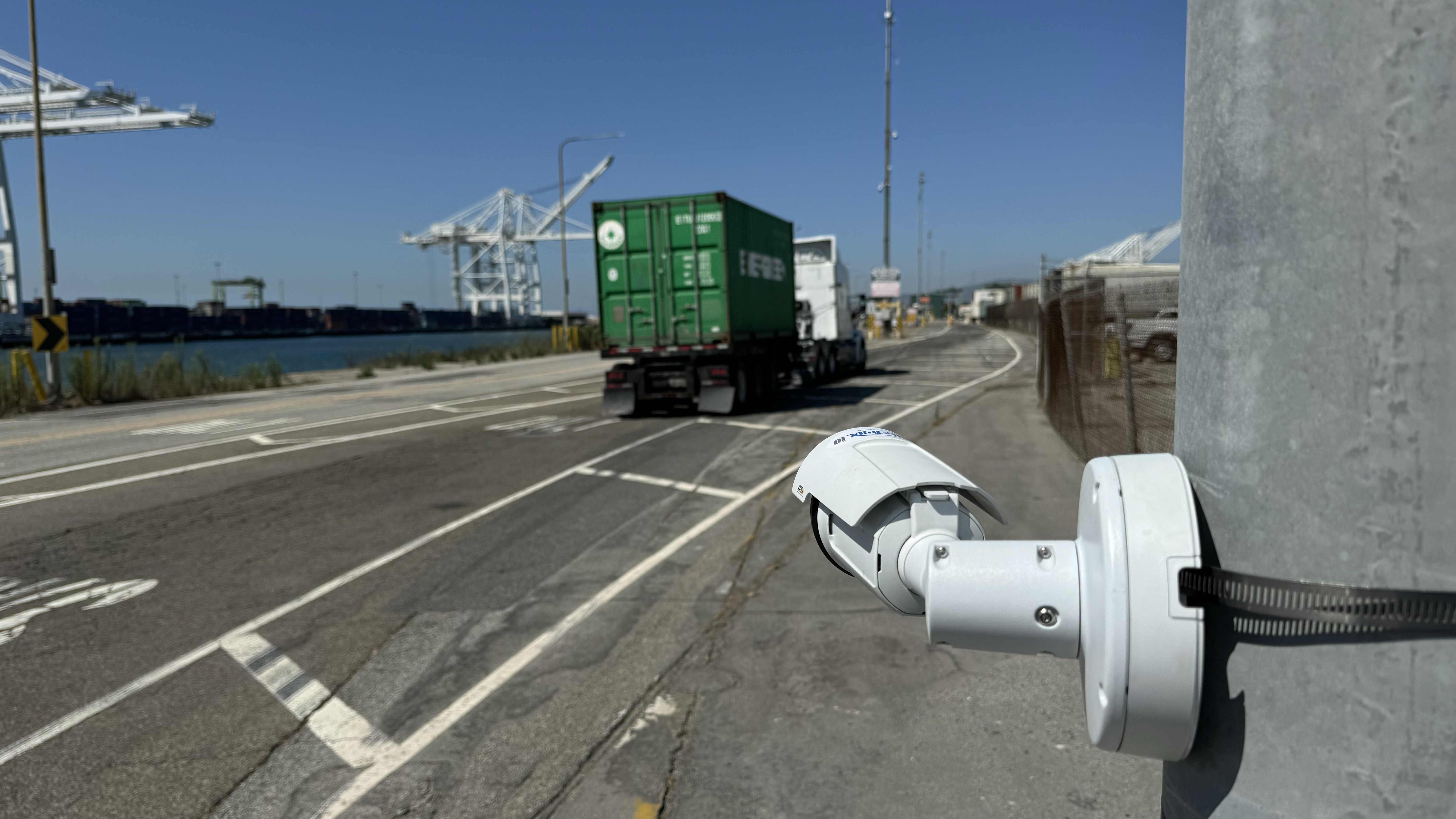
Install and commission cameras so that SiteTrax.io receives sharp, complete, well-lit views of the identifiers your project is configured to read. This guide covers fixed Gate and Bring Your Own Camera (BYOC) installations, vehicle-mounted Drive cameras, and camera positioning for Mobile and Snap capture.
Design principle: choose the capture position around the identifier, its motion, and the required evidence. A camera that shows a vehicle clearly does not necessarily show its text clearly enough for OCR.
Project-specific acceptance: minimum character pixel height, allowable viewing angles, usable capture duration, and commissioning pass rates must be agreed with SiteTrax.io for each project. There is currently no universal SiteTrax.io threshold for these values. Numerical examples below explain design calculations; they are not acceptance criteria or performance guarantees.
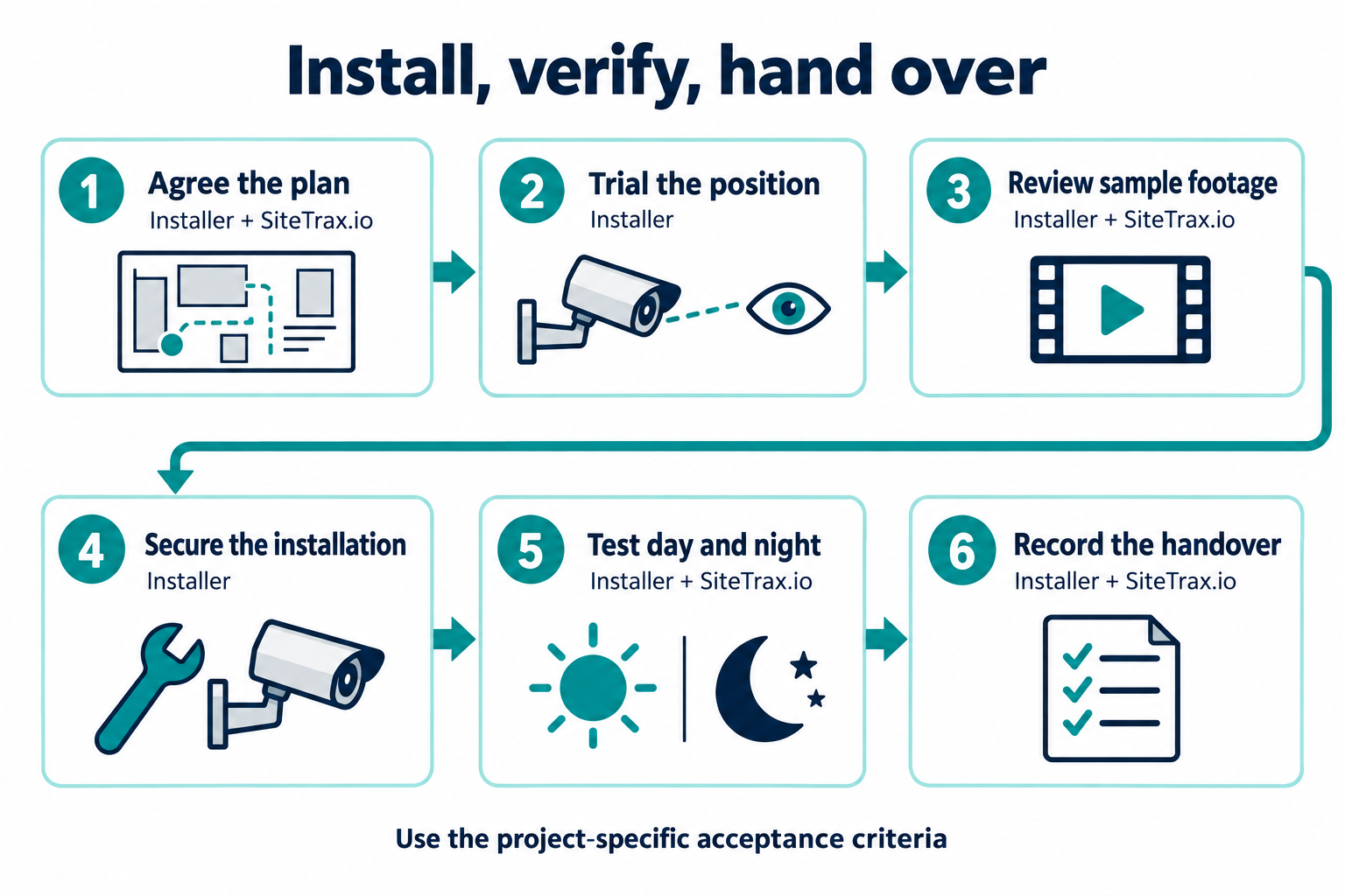
Suggested installation sequence. Agree responsibilities and acceptance criteria for your project. Select the image to enlarge.
1. Establish the deployment requirements
Read the Gate Camera Installation Requirements and Guidelines before planning fixed hardware. For a third-party camera, also complete the BYOC evaluation. Confirm the following with the site owner and SiteTrax.io before drilling holes or selecting a lens.
- Required outputs: container ID, chassis ID, trailer ID, USDOT number, license plate, or other explicitly configured text. Photograph representative markings and record their location, orientation, smallest character size, and height above the road. Confirm support for specialized assets or text with SiteTrax.io; this guide does not establish support for every OCR application.
- Traffic envelope: each lane and direction, vehicle dimensions, lateral wandering, stopping locations, maximum operating speed, reversing, queues, tailgating, and simultaneous adjacent traffic.
- Capture conditions: minimum and maximum target distance, direct sun, shadows, headlights, night lighting, rain, dust, spray, seasonal vegetation, and expected vibration.
- Infrastructure: mounting surface, service access, power, camera power requirements, network route, upload capacity, and ownership of maintenance and remote configuration.
- Processing and evidence: project, camera identity, required asset types, direction mapping, coordinates, timestamps, upload destination, retention, and downstream delivery.
- Acceptance plan: representative test population, independently verified identifiers, thresholds per asset type and condition, exception treatment, and the person responsible for sign-off.
Mark each camera, capture zone, light, traffic direction, and obstruction on a site sketch. A capture zone is the part of the vehicle path in which the required marking is visible, sufficiently detailed, sharp, and correctly exposed. The full camera view will usually be larger than this zone.
2. Select the views and camera positions
Fixed gates: assign views by lane, direction, and target
The Gate installation guide recommends at least one camera per lane and identifies two cameras per lane as best practice. Design dedicated coverage for each direction. Allocate the views to the identifiers that must be captured; do not assume two cameras in arbitrary positions will capture every asset.
Gate Operations acknowledges that a single camera can support both directions when placement and configuration capture them reliably. Treat this as a project-specific design that needs validation, including opposing traffic and occlusion. It does not replace the dedicated-camera baseline.
| Target | Placement approach | Verify with real assets |
|---|---|---|
| Rear container and chassis markings | The Gate guide suggests approximately 3 ft (about 1 m) mounting height for capturing the backs of containers and chassis. Use this as an initial camera-height reference. | The low chassis marking and the required container marking are both visible; tires, mudguards, chassis beams, and rear fittings do not block them. |
| Container-only rear markings | The Gate guide suggests approximately 4–6 ft (about 1.3–2 m). Set the final height and aim for the actual marking positions. | Required horizontal and vertical text remains fully in frame across the fleet and lane envelope. |
| Trailer IDs and side markings, including USDOT | Choose the side of the lane that exposes the required panel. Aim toward the marked surface, allowing enough context for the configured detector. | Tractor, trailer, and carrier identifiers are not confused; logos, straps, adjacent equipment, and articulation do not hide the target. |
| License plates, where configured | Use a view and exposure suited to the plate position and reflective material. A separate plate view may be needed. | Plate text is readable in headlights and darkness as well as daylight; an exposure that reads a plate may leave container markings too dark. |
| Yard inventory or other configured OCR | Map the required asset faces and accessible viewing routes. Arrange additional views where one position cannot see all required markings. | Coverage includes the intended rows and heights. Hidden or inward-facing identifiers require another view or an exception process. |
These Gate heights are starting recommendations for the stated rear-view use cases, not universal dimensions for side views, plates, elevated structures, or vehicle-mounted cameras. Measure camera height at the lens center and record the final value.
Choose geometry before adjusting software
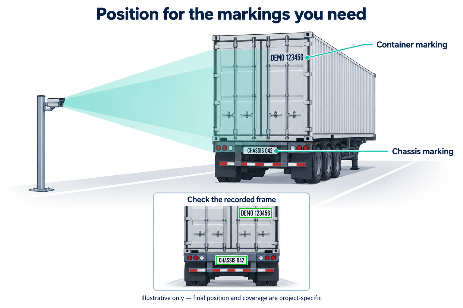
Illustrative marking locations and field of view; not to scale. Identifiers are fictional. Confirm coverage of your actual assets; additional views may be needed.
- Place a representative asset in the proposed capture zone under controlled site conditions. Identify the exact marked surface to be read.
- Temporarily position the camera at the proposed height and offset using a secure trial mount. Observe the actual recording stream.
- Aim as nearly perpendicular to the marked surface as practical. Reduce sideways perspective and excessive downward tilt. Level camera roll so the scene is not unnecessarily rotated; naturally vertical container text should remain fully visible.
- Check the nearest and farthest target positions, the highest and lowest markings, and both edges of the permitted vehicle path. Allow margin for movement without sacrificing text detail.
- Check that barriers, gate arms, posts, protective bollards, mirrors, and passing vehicles cannot mask the identifier at the required moment.
- If one view cannot meet all requirements, change the position, narrow its assignment, or add another view. Do not compensate for an obstructed or tiny identifier by increasing OCR confidence thresholds.
For a flat target facing along a lane, a useful geometry estimate is horizontal angle = atan(lateral offset / forward distance) and vertical angle = atan(height difference / horizontal ground distance). Use the height difference between the lens and the target marking, not simply height above ground. These estimates change when the asset turns or the text is on a side panel.
For license-plate capture, Axis recommends keeping the combined camera-to-travel angle below 30°. This is external plate-camera guidance, not a SiteTrax.io limit for container, chassis, or generic OCR. Minimize obliquity and validate the final geometry with SiteTrax.io. See Axis: License plate capture.
3. Select the lens, framing, and focus
The SiteTrax.io API — Input (Video) recommends 1920 × 1080 at 30 frames per second and specifies a lens of 6 mm or longer, warning about distortion with lenses below 5 mm. For a fixed/BYOC design, use that guidance and confirm the sensor, working distance, and field of view with SiteTrax.io. Do not substitute a phone's advertised equivalent focal length for an industrial camera's physical lens specification.
- Frame the required asset region with sufficient context for the configured detector. Do not crop down to isolated letters without SiteTrax.io confirming that the detector can operate on that view.
- Use optical lens selection or optical zoom to obtain usable text detail. Enlarging a low-resolution preview with digital zoom does not recover missing character strokes.
- Inspect individual frames from the actual saved/uploaded video at native pixel size. Check the smallest and most distant required text, not only the largest identifier near the center.
- Measure character height in pixels and record it for SiteTrax.io review. Check edge distortion and foreshortening as well as pixel count.
- Focus on the target marking within the capture zone. Verify the near and far limits remain sharp, and repeat under night illumination. If autofocus hunts between vehicles, agree a stable focus configuration with the camera supplier and SiteTrax.io.
Illustrative sizing calculation: with a 1080-pixel-high image covering 3.0 m vertically at a flat, face-on target plane, a 0.10 m character occupies approximately 1080 × 0.10 / 3.0 = 36 pixels. At a 6.0 m vertical field it occupies about 18 pixels. This estimates sampling only; perspective, compression, lens quality, focus, and motion can still prevent a read. See Edmund Optics: Resolution.
Cognex's OCRMax guidance illustrates why OCR systems specify character size in pixels. Its product-specific recommendations must not be adopted as SiteTrax.io acceptance thresholds.
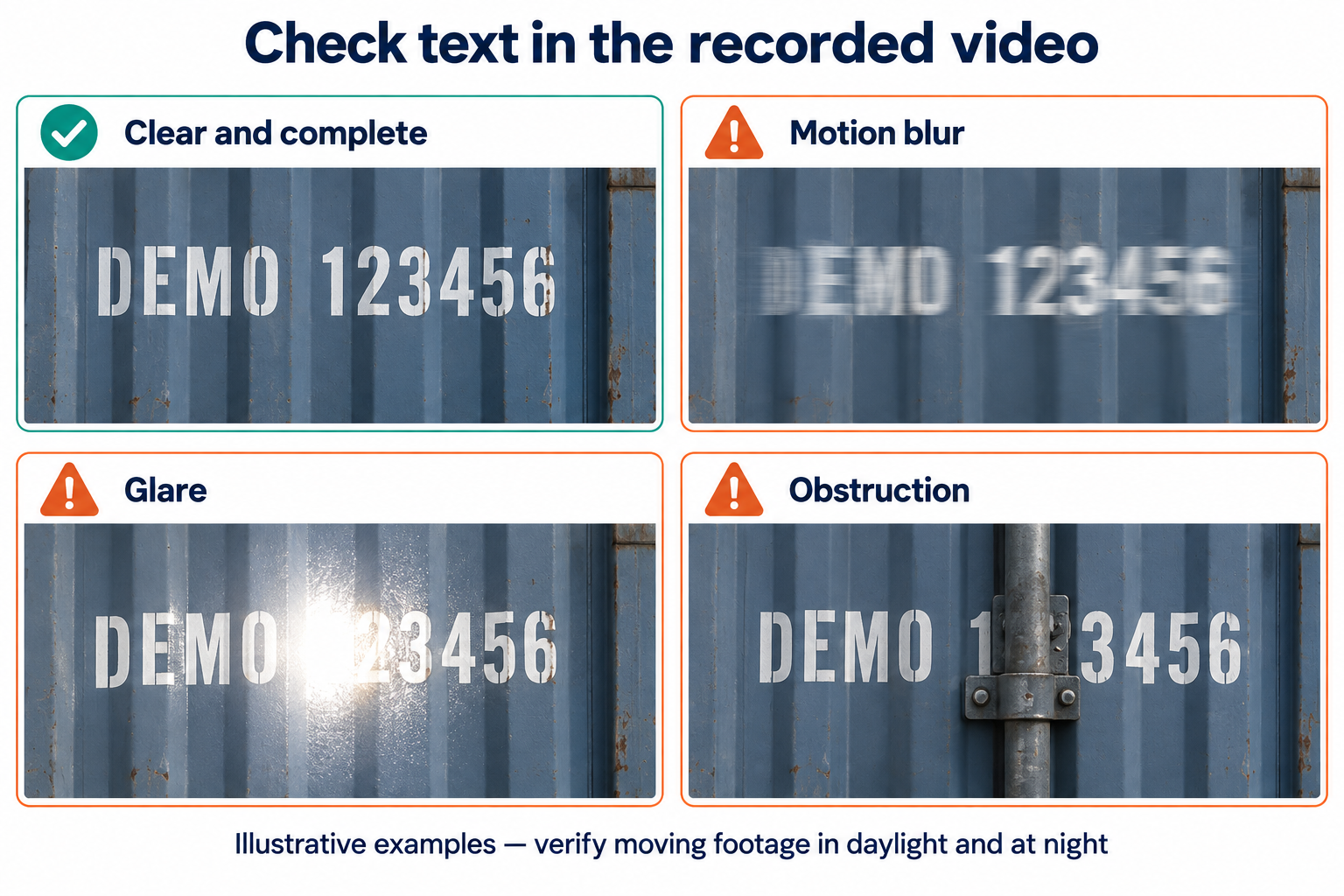
Simulated image-quality examples, not SiteTrax.io detections or OCR test results. Inspect actual recorded frames at the expected speed in daylight and at night.
4. Control motion and illumination together
Speed, shutter, and recording duration
For fixed Gate installations, the Gate guide recommends traffic at 10 mph (16 km/h) or below, using suitable site traffic controls. Position the read zone where the intended speed is actually achieved. A vehicle accelerating after a stop or bouncing on a speed bump may still produce unusable frames.
Frame rate and exposure are different. Thirty frames per second describes how often images are captured; shutter time describes how long each image gathers light. A 30 fps video can still contain motion-blurred text. Shorten exposure until moving character edges remain distinct, then provide enough illumination for that exposure. See Edmund Optics: Camera sensors, frame rate, and shutter speed.
Illustrative motion calculation: for lateral movement of 4.47 m/s (10 mph) across a target plane spanning 4 m over 1920 pixels, image motion is approximately 2,146 pixels/s. At 1/1000 s exposure, motion during exposure is about 2.1 pixels; at 1/250 s it is about 8.6 pixels. This is a simplified transverse-motion example, not a recommended shutter setting. Approach motion, perspective, and camera movement require separate evaluation.
Coordinate event detection, pre-event recording, post-event recording, and clip segmentation with SiteTrax.io. Capture must start before the identifier enters the usable zone and continue until the required views are recorded. Test slow traffic, stopping, reversing, and closely spaced vehicles. The theoretical available frames are frame rate × usable path length / speed; frames outside the focus or exposure limits do not count as useful evidence.
Lighting for painted and reflective text
The existing Gate guide recommends a 5,000-lumen, 7,000 K LED light positioned approximately 20 ft from the scanned objects. Use that as a published starting recommendation, then validate the actual installation. Lumens describe total light output; they do not specify the illumination reaching a marking. Beam spread, angle, distance, surface reflectance, weather, and exposure determine the result. There is no universal lux target established here.
- Illuminate the entire usable capture zone, including low chassis text and the extremes of the lane. Aim lights to avoid hard shadows from door hardware and underframes.
- Keep the light source out of the camera's direct view and manage driver glare. Test on wet surfaces and light-colored as well as dark assets.
- Inspect recorded moving text for flicker bands, bright hotspots, clipped white areas, and noise. Select lighting and exposure settings that work together; a visually bright scene is insufficient.
- Test the actual painted, printed, or reflective markings under the intended visible/IR lighting. Do not assume an IR plate illuminator will preserve contrast on every painted asset identifier.
- Check daylight, dusk, night, and day/night switching. Retest after changing illuminator position, intensity, camera exposure, or lens settings.
Retroreflective plates return light toward its source, so Axis recommends placing external IR illumination near the plate camera. Excess illumination or gain can wash out plate characters. Axis also warns that some WDR implementations create motion artifacts; disable WDR or use a suitable motion-safe mode for plate capture according to the camera manual. These plate-specific choices need separate validation for other markings. Source: Axis: License plate capture.
The AXIS Q1800-LE manual provides examples of balancing shutter, gain, focus, and illumination. Follow the manual for the camera actually installed; its menu names and numerical defaults are not SiteTrax.io-wide settings.
5. Install the fixed mounting hardware
Use a qualified installer for the structure, electrical work, and access equipment involved. Follow the selected camera, bracket, enclosure, and power equipment instructions. This procedure does not specify structural loads, anchor sizes, torque, or electrical protection for an unknown installation.
- Prepare the work area. Coordinate a lane closure or controlled work zone. Keep personnel and equipment clear of vehicle paths, gate movement, and overhead hazards.
- Verify the support. Use a rigid surface suitable for the complete camera, bracket, enclosure, lighting, and environmental loads. Avoid loose fencing, flexing sheet metal, or vibrating machinery as unassessed supports.
- Mark the verified position. Transfer lens-center height, setback, and direction from the successful trial. Check service clearance and the full vehicle swept path before fixing the bracket.
- Install the bracket. Use manufacturer-approved fasteners and anchors appropriate to the substrate. Tighten to the specified torque. Install any required safety retention. Do not guess a torque value.
- Fit and aim the camera. Set pan, tilt, roll, zoom, and focus while viewing the intended recording profile. Tighten adjustment locks and recheck the view after tightening; the aim can move.
- Protect a low mount. Locate collision protection so it protects the camera without blocking the low identifier or restricting traffic clearance. Preserve safe access for lens cleaning.
- Weatherproof correctly. Use the approved outdoor enclosure, cable glands, seals, and junction boxes. Match glands to cable diameter, seal unused entries, and retain required drainage or ventilation. Arrange cable entries and drip loops to keep runoff away from connectors in accordance with the equipment instructions.
- Route and secure cables. Provide strain relief and a controlled service loop. Protect cable from abrasion, pinching, wheels, sharp edges, and moving gates. Use cable and conduit suited to the environment, observing the equipment's bend-radius and separation requirements.
- Verify power and connectivity. Confirm supply/PoE compatibility and total demand, including lights or heaters where applicable. Follow manufacturer requirements for grounding, bonding, and surge protection. Test the installed cable path and network connection under operating load.
- Record the installation. Label camera and cable ends. Photograph the bracket, camera aim, cable entries, lights, and final field of view. Retain the camera model, serial number, firmware, lens, and final settings in the handover record.
6. Adapt the installation for Drive, Mobile, and Snap
SiteTrax.io Drive
Follow the Drive Installation and Usage Guide for the supplied exterior camera, magnetic mount, USB connection, tablet dock, and vehicle power connection.
- Choose an exterior view of the required asset faces. Keep wipers, antennas, vehicle bodywork, reflections, and load attachments out of the capture area.
- Confirm the supplied mount is appropriate for the actual surface and operating conditions. Check attachment before each run and after a knock; do not assume a magnetic mount is suitable for every panel or speed.
- Route cables clear of steering, pedals, doors, airbags, and moving parts. Secure the tablet and dock without obstructing the driver.
- Confirm the live camera view before moving. Set up and operate recording while safely stopped, or use an appropriate passenger/operator procedure.
- Test the intended route, offset, turns, surface vibration, and relative speed. Change route or speed where identifiers blur or disappear. The fixed Gate mounting heights are not a Drive mounting specification.
- Verify recordings finish uploading, including after returning to Wi-Fi coverage. Arrange continuous-capture access and training through SiteTrax.io as described in Capture — Android.
Mobile and Snap
For handheld or temporarily supported capture, stand in a safe permitted position with a clear view of the asset and required identifier. Hold the device steady, keep the lens clean, avoid digital enlargement as a substitute for suitable distance, and verify focus and glare in the preview. Include the complete marking and enough asset context for detection.
Snap is documented for three-second, single-asset captures. Use the Snap tutorial to check the preview and upload workflow. Continuous yard scanning belongs to the enabled Android Capture workflow. Do not extrapolate fixed-camera lens dimensions to a phone without confirming the capture device with SiteTrax.io.
7. Confirm SiteTrax.io ingestion and project setup
A readable local preview is only the first check. The delivered video must preserve the same useful detail and reach the correct processing configuration.
- Confirm project and camera identity, required processing types, capture coordinates, and direction interpretation with SiteTrax.io. Record changes using the principles in Organization Configuration.
- Verify the delivered MP4 follows API — Input (Video): recommended 1080p/30 fps, clips no longer than the recommended one minute, required creation-time metadata, and GPS subtitle data or the agreed static-camera override. Confirm codec and any deviations during integration.
- For BYOC, test the agreed S3 upload path and processing flow using the BYOC guide. Camera/network compatibility alone does not prove ingestion compatibility.
- Verify sustained upload capacity during busy periods. Check whether buffering and recovery are supported by the selected equipment, then test the agreed recovery procedure for an upload interruption.
- Review the resulting video and asset record in SiteTrax.io Intelligence. Use Navigating the Intelligence Interface for Videos, Assets, project/date filters, and record feedback.
- If downstream delivery is in scope, verify a real commissioned detection arrives with the expected fields at the configured destination. Refer to API — Output (JSON) for integration details.
For entry/exit uses, test each actual direction and reversing separately. Camera/project designation and image-relative heading are different evidence. Follow Gate Operations for direction mapping and pairing; a name such as “North Gate” does not establish direction.
8. Commission with representative traffic
Agree the sample size and pass criteria with SiteTrax.io before testing. Use real assets with independently verified identifiers. Include both routine and difficult conditions; a parked daytime example is not sufficient to accept a moving, day-and-night installation.
| Test group | Include | Record |
|---|---|---|
| Coverage and geometry | Every lane and direction; near/far and left/right positions; required asset families, text heights, and orientations. | Complete target visibility, pixel size, focus, obstructions, and usable capture zone. |
| Motion | Normal and maximum agreed speed; stop/start; reversing; close following and adjacent traffic where applicable. | Blur, capture timing, missed passages, repeated results, and direction correctness. |
| Lighting and environment | Day, low sun/backlight, dusk, night, headlights, and relevant wet or adverse conditions when available. | Exposure, glare, shadows, flicker, day/night transitions, and any condition not yet tested. |
| End-to-end processing | Upload, processing, image/video evidence, project/camera attribution, coordinates, timestamps, and configured downstream delivery. | Source clip and detection references, exact expected/read identifiers, processing outcome, and delivery failures. |
| Operational recovery | Approved restart or connectivity-recovery test and post-maintenance aim check. | Return to capture, upload recovery, preserved settings, and exceptions requiring intervention. |
Keep an independent passage log with expected identifiers and asset types. Compare it with source clips and processed results. Separate these measures and publish their denominators:
- Capture coverage: eligible physical passages with usable identifier evidence divided by all eligible passages in the test log.
- End-to-end correct identification: eligible passages with the complete correct required identifier in SiteTrax.io divided by all eligible passages. Where two identifiers are required, record both individual and paired outcomes.
- Read correctness: independently verified correct returned identifiers divided by the returned identifiers assessed, with the treatment of repeated readings stated.
- Exceptions: missed capture, unreadable text, wrong identifier, incomplete required pair, duplicate handling, incorrect direction, and upload/processing failure reported separately.
Do not label the share of A0 records as OCR accuracy. A0 indicates acceptance under processing rules, not independently verified truth. A stored row is not necessarily a unique physical passage, and combined processing can include synthetic pair records. Apply How Intelligence Uses SiteTrax.io Data when assessing outcomes.
Resolve failed cases and repeat the affected tests. Record exclusions rather than silently removing difficult assets. If an essential condition cannot be tested, identify that limitation and the required follow-up before declaring full acceptance.
9. Troubleshoot the image before changing OCR rules
| Symptom | Check first | Corrective action |
|---|---|---|
| Identifier too small or missing at an edge | Native recorded frames, lane extremes, lens and view width. | Reposition or adjust optical framing; add a dedicated view if context and text detail cannot coexist. |
| Sharp when stopped, blurred when moving | Exposure time, actual speed, vibration, and lighting. | Shorten exposure, improve light, stabilize the mount, or reduce speed; retest moving traffic. |
| One distance sharp, another soft | Focus and required depth of field. | Refocus or redesign the usable zone/lens configuration. Verify near and far limits. |
| Night failures only | Saved night video, illumination coverage, reflective hotspots, contrast, and focus. | Adjust light position/output and exposure together. Test real markings after day/night switching. |
| Ghosted or banded characters | WDR, lighting flicker, and image processing. | Test appropriate camera modes and lighting settings with the supplier; compare moving recorded frames. |
| Intermittent occlusion | Queueing, adjacent lanes, gate hardware, and asset structures. | Move the capture zone or provide another view; tuning cannot reveal hidden text. |
| Readable local video, no expected record | Upload completion, delivered format/metadata, project configuration, access, and date filters. | Follow the Troubleshooting Guide and BYOC/API ingestion checks. |
| Wrong entry/exit classification | Actual movement, heading, role designation, and direction mapping. | Review configuration with SiteTrax.io and retest both directions and reversing. |
For escalation, provide the project, camera model/identity, timestamp and timezone, expected identifier/type, source clip or detection reference, a sample failed frame, current settings, and installation photos through the approved support channel. Do not include passwords, tokens, access keys, or secrets.
10. Handover and maintenance
Before handover, retain the site sketch; camera/lens inventory; final mounting heights, offsets, distances, and angles; recording and exposure settings; day/night sample clips; lighting arrangement; network/power details; direction mapping; commissioning log; agreed acceptance criteria; unresolved limitations; and customer/SiteTrax.io ownership contacts.
The customer owns site infrastructure and physical camera maintenance. SiteTrax.io provides processing, orientation/detection advice, and camera-tuning guidance; upgrade and remote-management responsibilities must follow the agreed deployment model. See the Gate responsibilities and BYOC responsibilities.
- Set a site-specific inspection schedule for lens/window cleaning, fasteners, alignment, seals, cable protection, illuminators, and vegetation or new obstructions.
- Recheck after impacts, storms, maintenance, changes to lighting or lane geometry, firmware changes, and camera replacement.
- Compare the current view with the accepted reference image and repeat affected day/night moving tests after changes.
- Review capture gaps and exceptions routinely. A reduction in stored activity is a reason to investigate, not proof of a hardware outage.
- Maintain a manual exception process for missing, damaged, obscured, or otherwise unreadable markings. OCR cannot reconstruct evidence that the camera did not capture.
Source notes
Reviewed 23 September 2026. SiteTrax.io product and deployment statements above are linked to the applicable documentation at the point of use. Current Intelligence guidance is used for application navigation and record interpretation; the retired service portal is not the commissioning destination.
External references provide imaging principles and manufacturer-specific examples, not certification of a SiteTrax.io deployment: Axis license plate capture; AXIS Q1800-LE manual; Edmund Optics resolution; Edmund Optics camera sensors; and Cognex OCRMax configuration. The applicable hardware manuals and the project-specific SiteTrax.io acceptance plan govern the final installation.